Operation KEG Part 6: It’s Alive!

tux_cant_look tux_celebrates

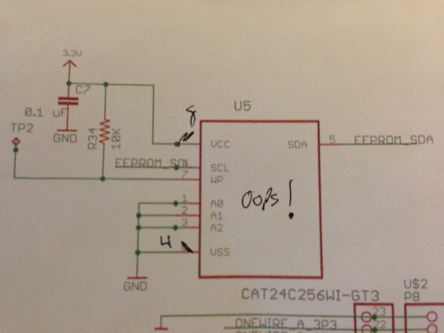
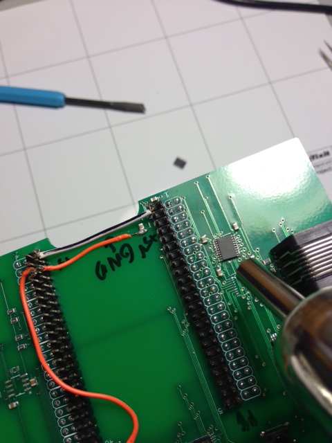
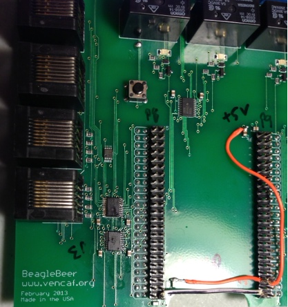
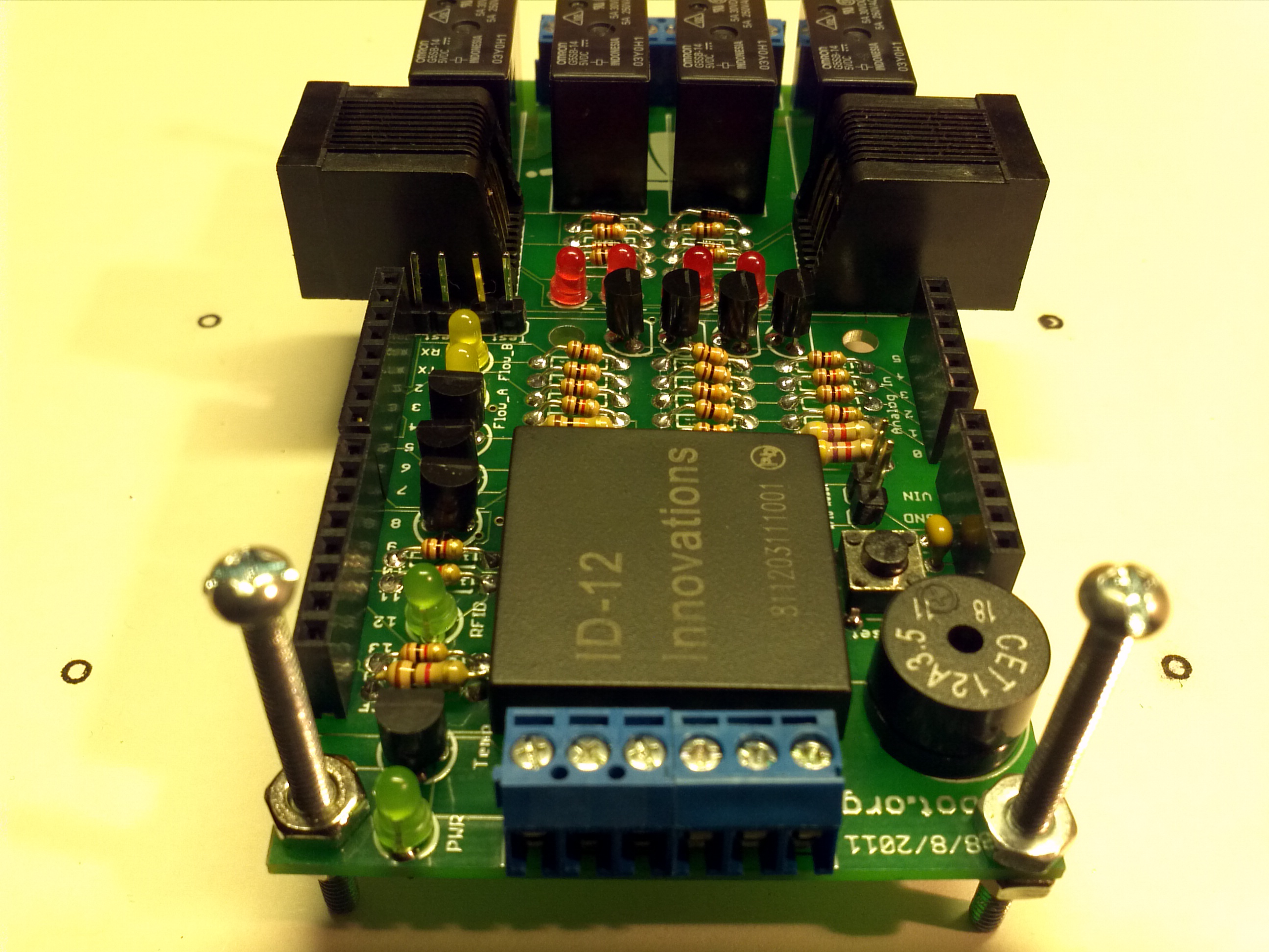
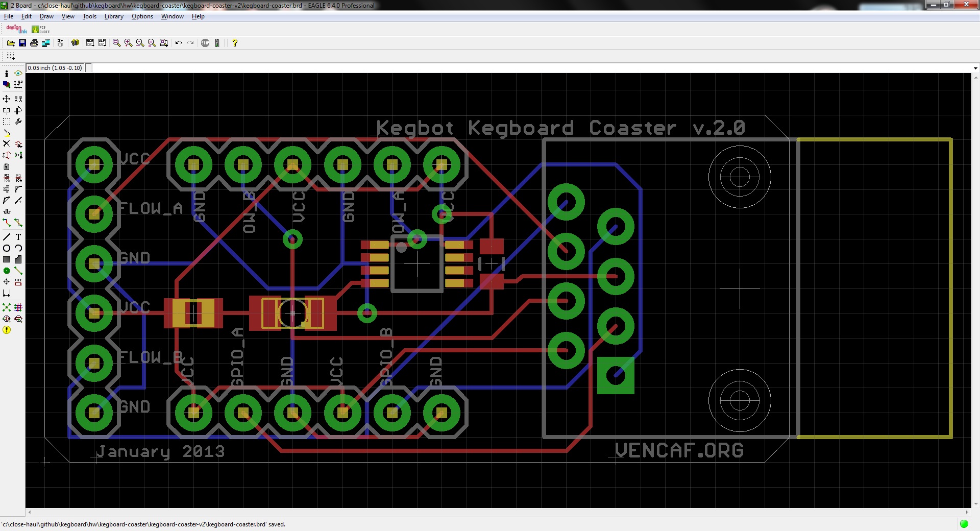
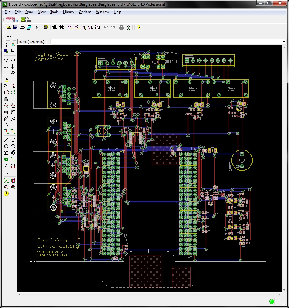
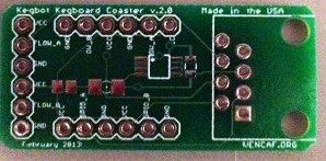
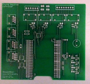
The BeagleBeer Flying Squirrel Controller, first introduced in Operation KEG Part 3: Bespoke Kegbot, required enough rework that I decided to re-spin the printed circuit board (PCB). I corrected the design errors uncovered during the debugging process in the schematic, remade the PCB layout and manufacturing files, and dispatched the design files (available on Github) to Sunstone Circuits. Two weeks later, on Wednesday 24 April, I arrived home to find a small UPS package containing two BeagleBeer Version 2 PCBs on my doorstep. I handed over a bare PCB and the parts kit to my co-worker Sebastian Patulea, who graciously volunteered his time after hours to assemble it in exchange for lots of free beer. He had finished soldering on the components by Friday evening.

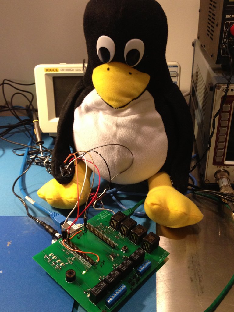
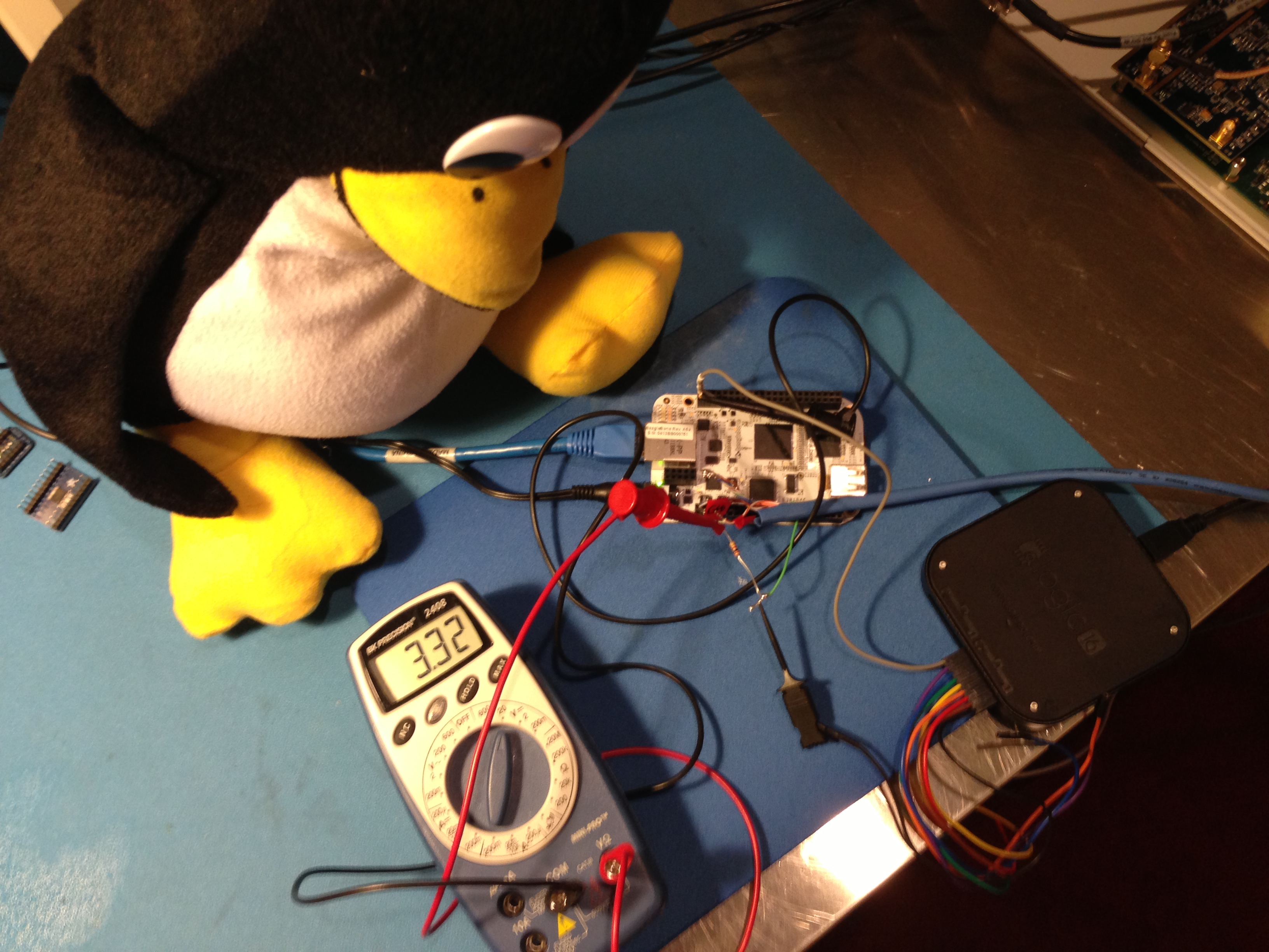
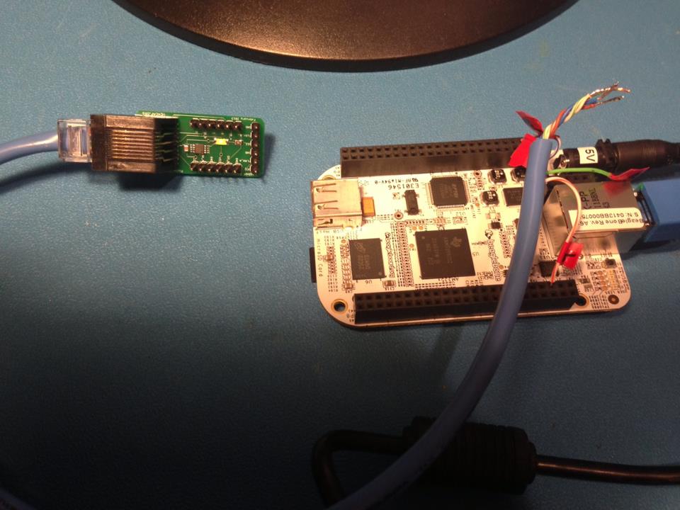
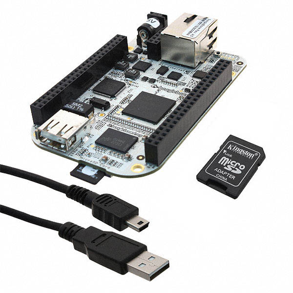
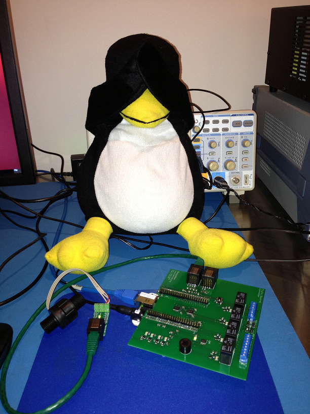
A business trip to Seattle prevented the much-anticipated Smoke Test from taking place immediately. (You may recall that it failed spectacularly the first time around.) My loyal lab assistant waited impatiently as I stumbled around in a post-redeye catatonic stupor on the evening of Wednesday 1 May. I apologetically informed Tux that we would not be able to test with beer during Venture Café the next day, but if he could just sit tight for one more week, his fervent wish would most likely be granted. In order to humor him, I connected the BeagleBeer Version 2 to the BeagleBone computer and, after pouring myself a shot of rye whiskey, turned on the power.

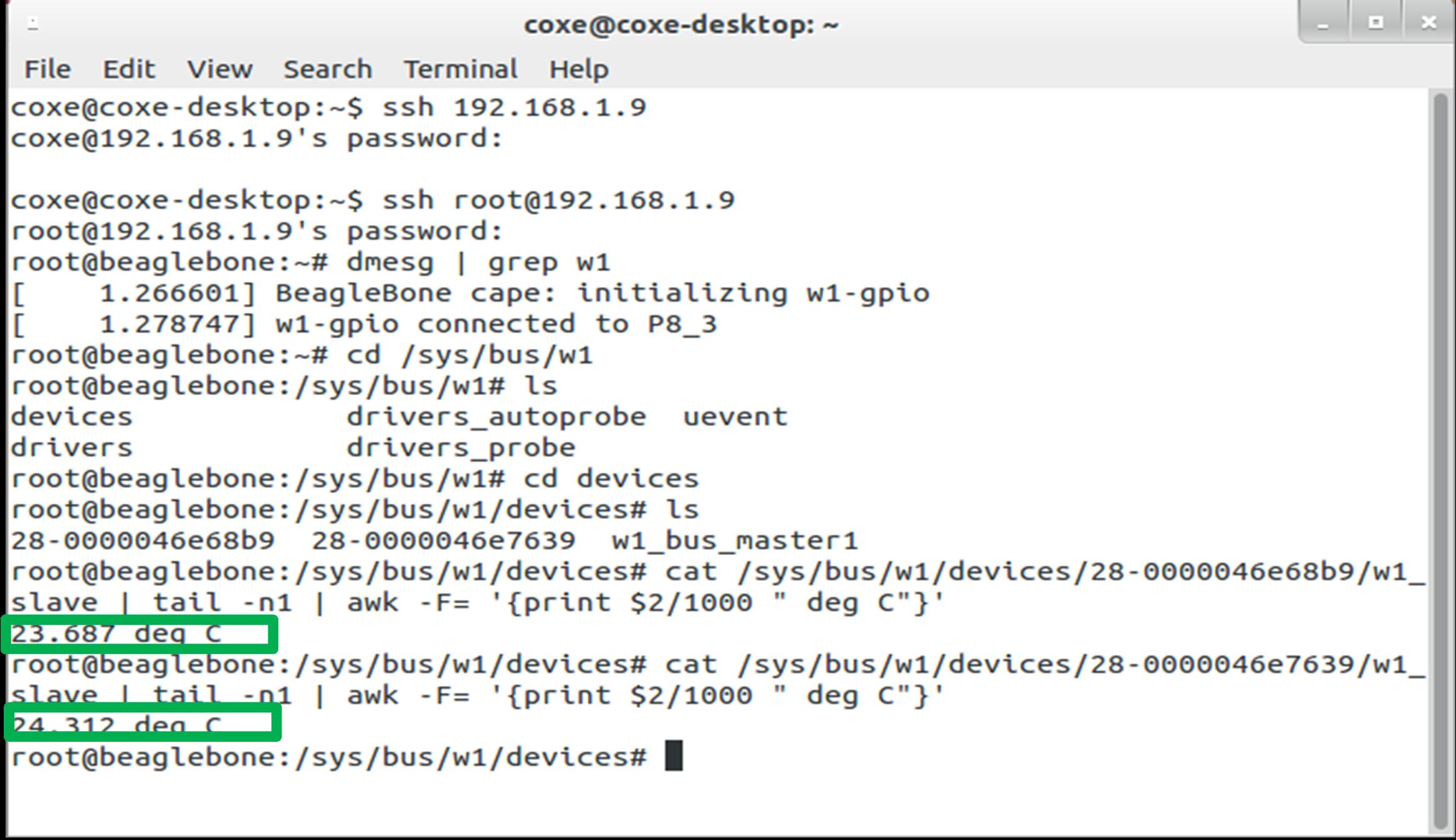
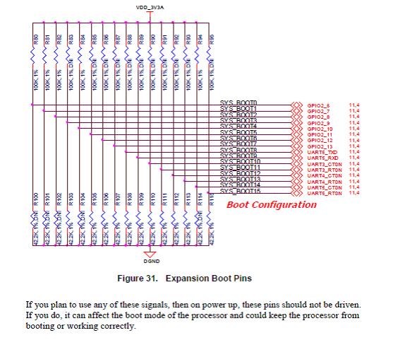
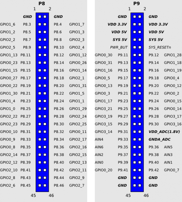
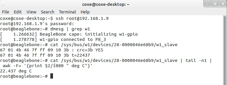
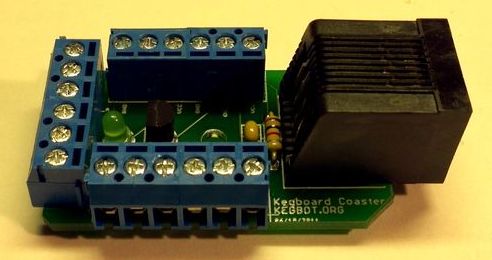
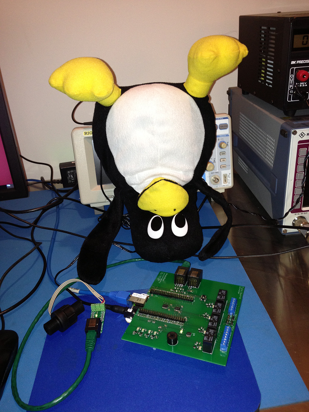
At first, Tux couldn’t bear to look. But it soon became clear that all of the fixes outlined in Operation KEG Part 5: Dum Spero Spiro! just worked. The BeagleBone boots with the BeagleBeer board attached now that none of the system boot I/O lines are being driven at power-up. Both temperature sensors, one on the Coaster board and a second on the BeagleBeer controller itself, happily reported temperatures when I queried the 1-wire slave devices from the command line. No dramatic blue smoke or melting plastic to speak of. Tux rejoiced. I drank more whiskey.

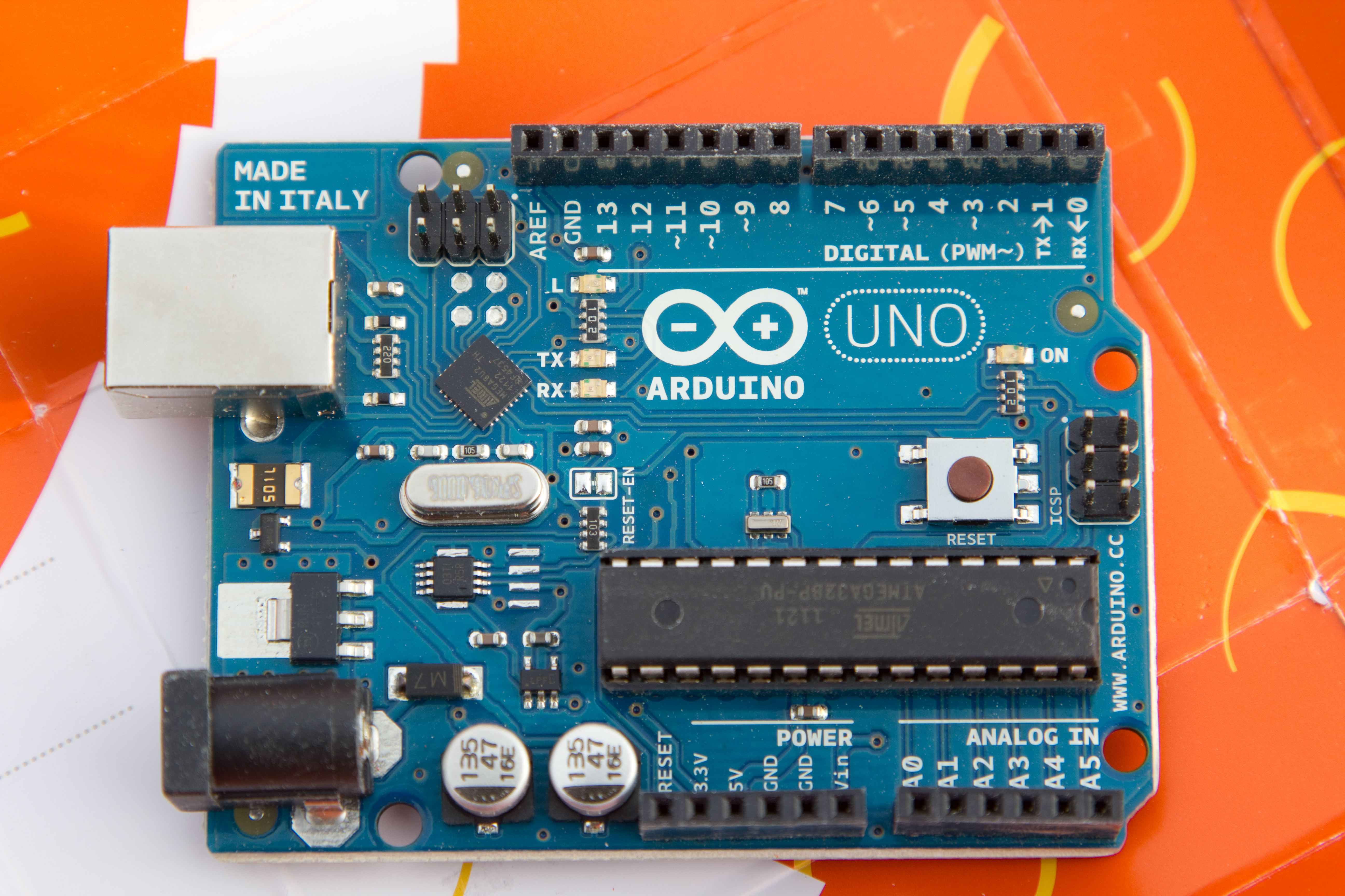
In order to perform a meaningful alpha test with beer during Venture Café, we needed to shift gears and focus our attention on the readout software. The Arduino in the Kegbot system controls the Kegboard with library of C programs. Blocks of Arduino code are referred to as sketches, all of which include the functions setup(), used for initialization, and loop(), the main execution loop. Because the BeagleBone has a more powerful processor and runs a full-blown Linux operating system, programs targeted to it have fewer restrictions. Nevertheless, maintaining the basic structure of an Arduino sketch has numerous advantages when interfacing to low-level hardware.

We had several reasonable choices of programming languages: 1) write a shell script to interact with Linux device drivers directly from the command line, 2) write a C or C++ program, 3) use the Cloud9 IDE included with the BeagleBone Angstrom Linux distribution to run bonescript, described on the BeagleBoard website as “a node.js-based language specifically optimized for the Beagle family and featuring familiar Arduino function calls, exported to the browser”, and 4) use PyBBIO, a Python library for hardware I/O support for BeagleBone. Although intrigued by the Node.js-based bonescript approach, I chose PyBBIO, as it seemed like a perfect excuse to finally learn Python.

The Python program for the first field test has 3 primary functions:
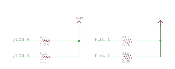
1. Configure the Flow Sensor A data line as a GPIO input and as a falling edge interrupt

2. Define the behavior of the flow sensor interrupt

3. Read out the 2 temperature sensors and print the temperature in both Celsius and Fahrenheit to the console once per minute

In order to avoid re-inventing the wheel, I took to Google in search of Python code for reading out the DS18B20 temperature sensors. A code sample from the Adafruit blog targeted to Raspberry Pi immediately presented itself. I modified the code slightly to accommodate multiple temperature sensors by adding the argument nsens to the readout functions.

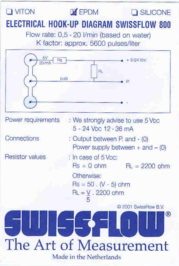
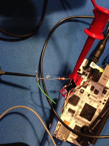
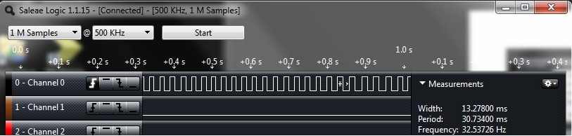
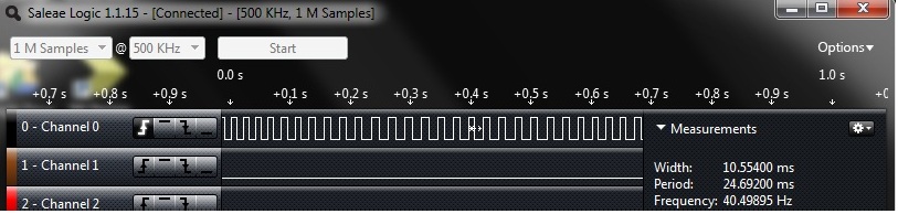
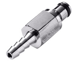
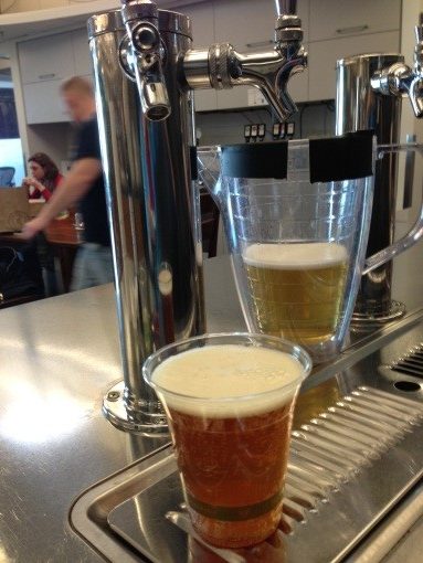
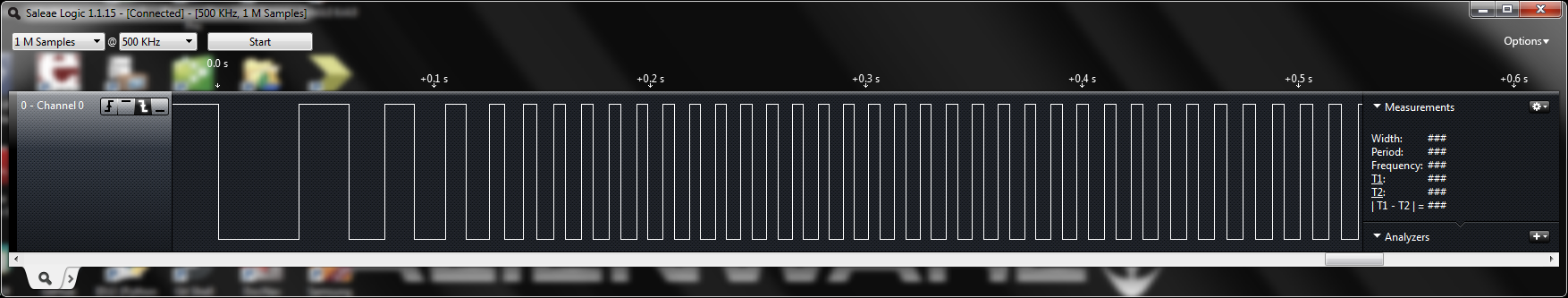
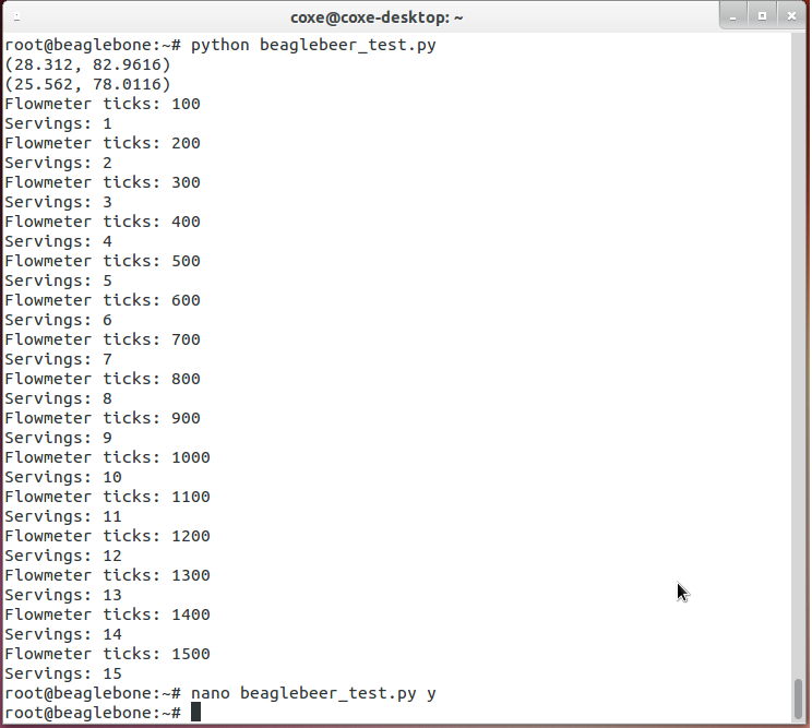
When beer flows through the Swissflow SF800 flowmeter, the meter emits approximately 5600 pulses per liter of liquid traversing the sensor. A 9 oz. Vegware cup = 266.2 ml = 1490 counts. A 250 ml serving of beer at Venture Café should register ~1400 flow sensor pulses. The interrupt service routine (ISR) fires every time the Flow Sensor A data line transitions from high (3.3V) to low (0 V). I included two print statements in the ISR to display the raw number of flowmeter ticks as well as the number of 250 mL servings dispensed to the console. To inspect the code in its “I’ve never programmed anything whatsoever in Python before this week” splendor, click here.

flow_test_setup

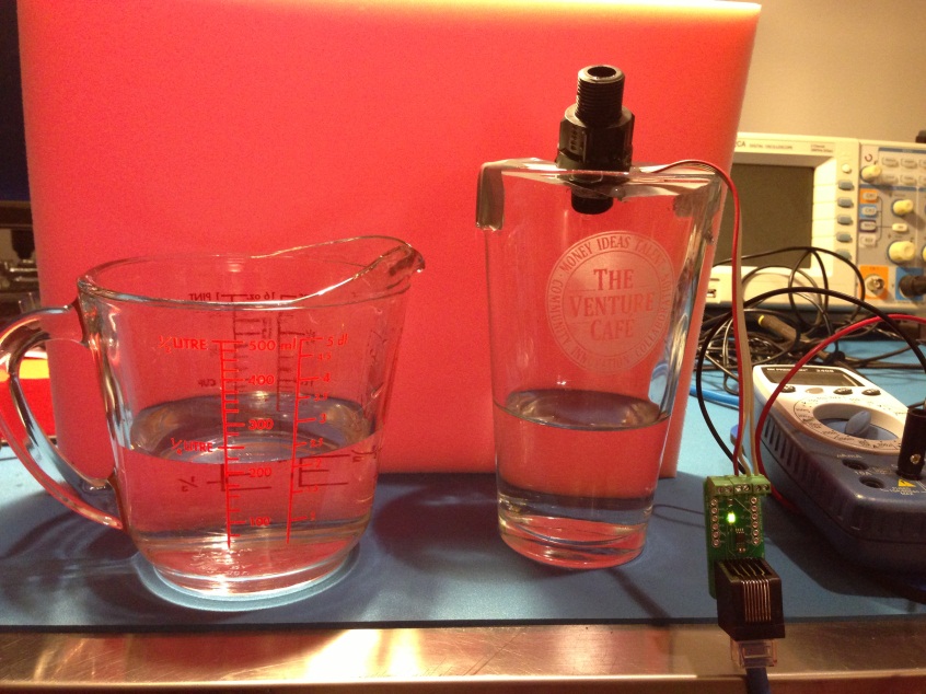
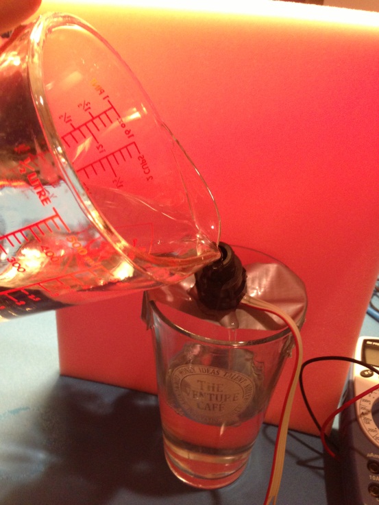
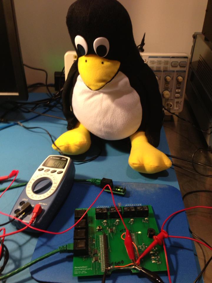
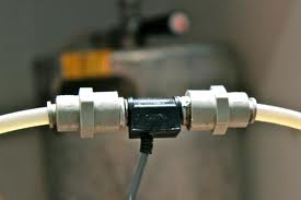
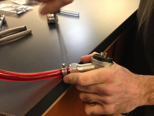
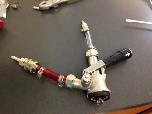
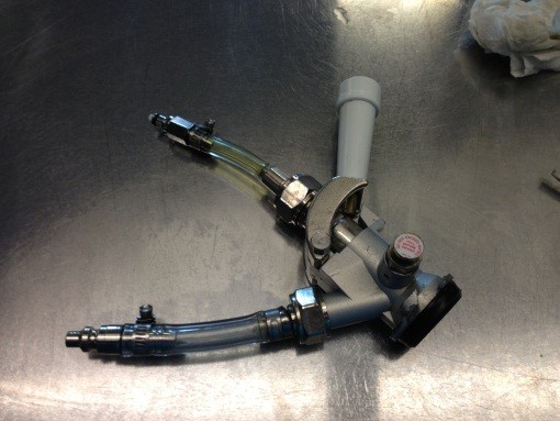
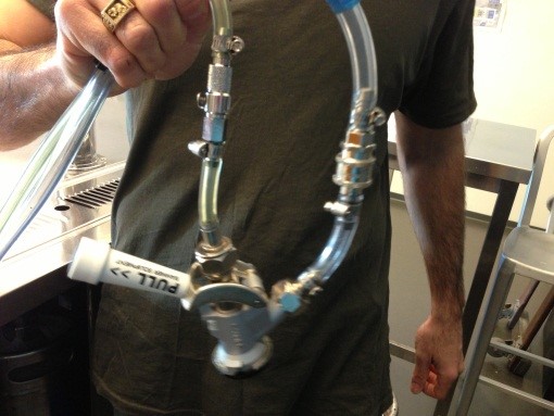
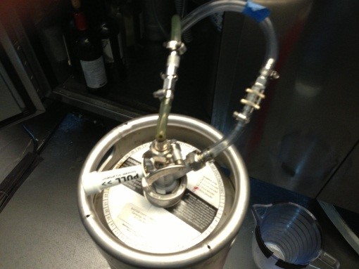
I busted out the quick and dirty flow testing setup again to ensure that this scheme behaved as expected. Lo and behold, it did! [I set a “serving” to be 100 counts to avoid pouring excessive amounts of water through the sensor.] The numbers in parentheses at the top of the display are the temperature readouts in the format (degrees Celsius, degrees Fahrenheit). The logic analyzer screen capture clearly shows the flow sensor pulse train.

beaglebeer_v2_flowsensor

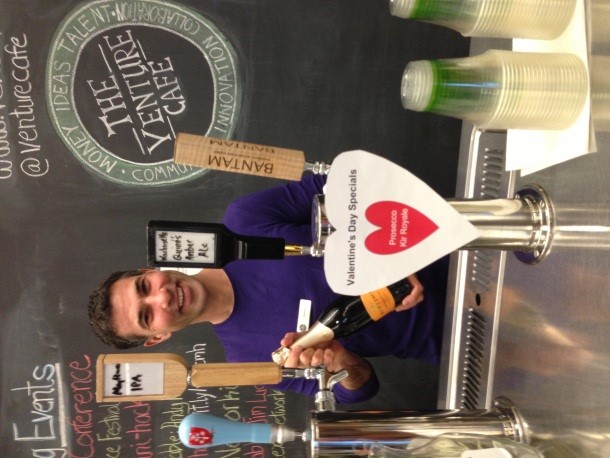
For the maiden beer test at the Café, both the BeagleBone and a laptop must be connected to the same LAN, which will require a wireless bridge to share a CIC WiFi link. I will log in to the
BeagleBone over an SSH connection from the laptop and the results will print out to an old-school terminal console. Please don’t be alarmed if you see Tux keeping watch over the hardware setup. In
addition to putting the system through the paces in a realistic environment, the Beer Experiment will also serve to calibrate the flow sensor. I’ll be able to change the number of counts per serving
on the fly as I dispense beer.

beaglebeer_v2_flowsensor_readout

Provided the test succeeds, we can forge ahead with end-to-end Kegbot integration:

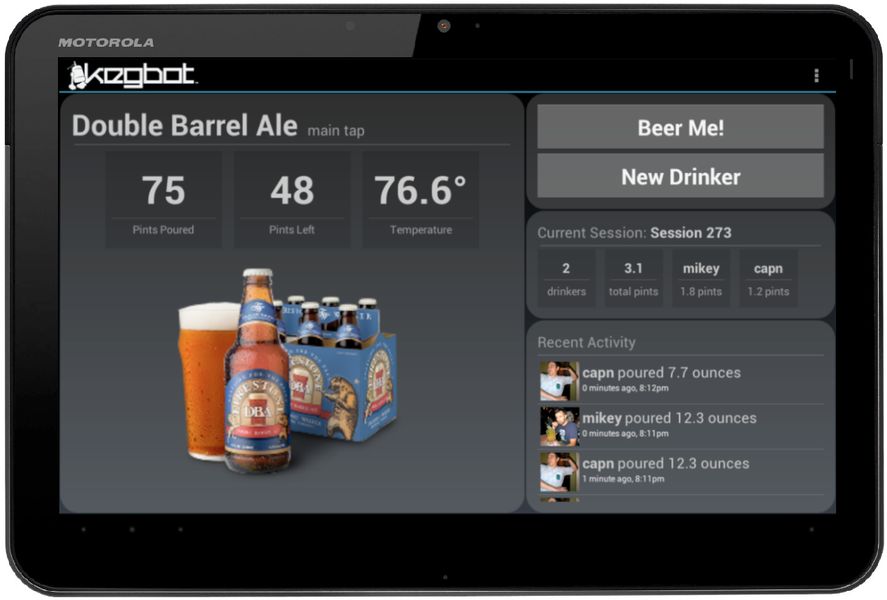
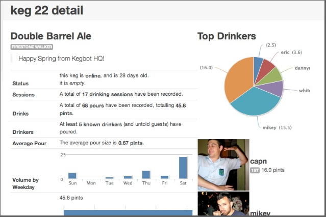
• Add a UART Packetizer function to send the temperature and flow sensor data to an Android tablet running the Kegbot app over a serial link (USB cable). The Android app will then sync to the Venture Café Kegbot server, a web app that resides in the Amazon cloud, over WiFi. The web server includes a backend database that will enable us to perform a wide array of beer consumption analytics.

• Add code to control the buzzer on the BeagleBeer controller so it can sing little songs on command to Café visitors.

• Add a “the keg is about to kick” warning for the bartenders to the Kegbot app.

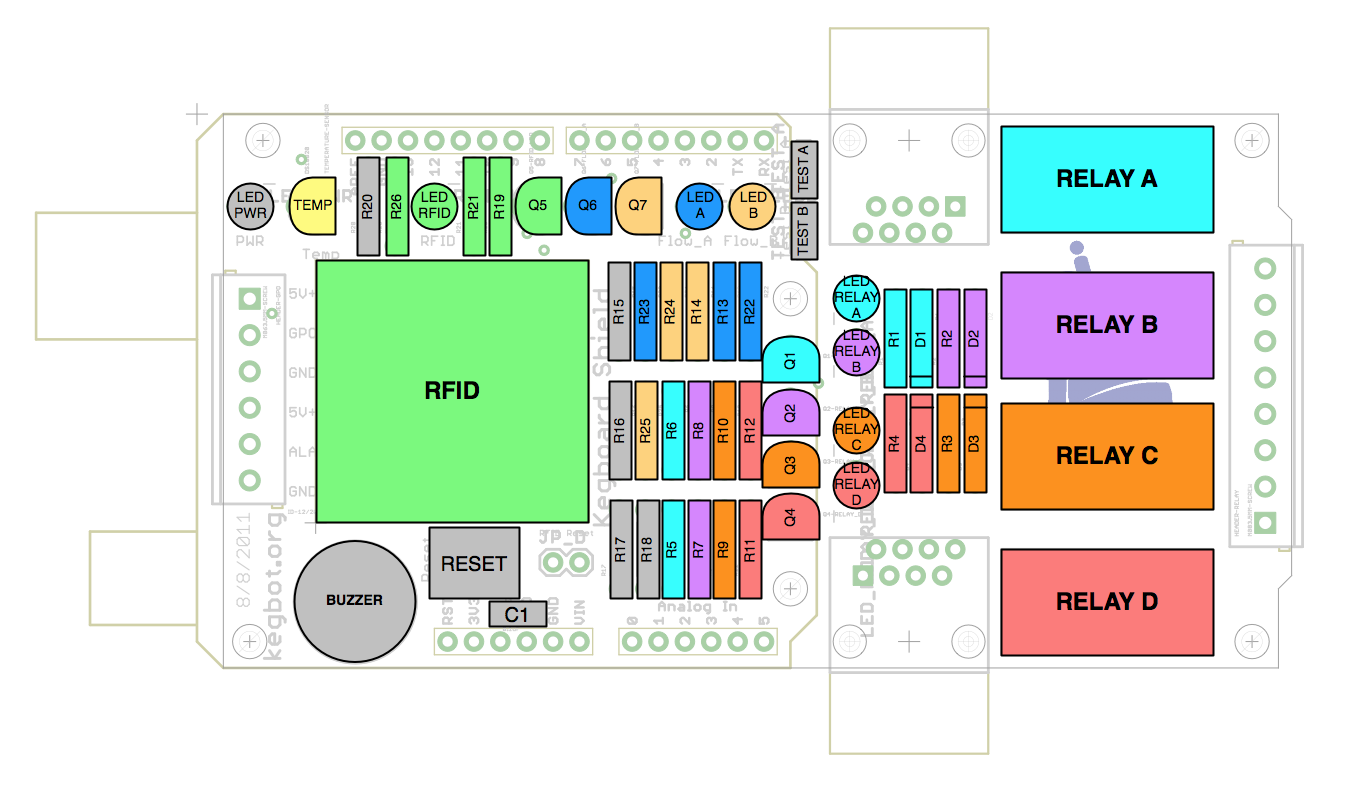
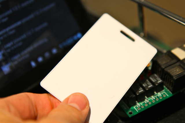
• Add support for the RFID card reader for drinker authentication.

• Add support for all four taps of the kegerator.

I’ll have enough material to ensure that the Operation KEG series will live on for the forseeable future. Good times!

Operation KEG Part 5: Dum spero spiro!

fet_level_shift

On Friday 5 April 2013 at 12:20 am, Tux the Polyester Penguin triumphantly declared: “Dum spero spiro!” after observing a string of valid temperature readings printed out in the debug console. Oddly, this Latin proclamation commonly attributed to Cicero happens to be the motto of the State of South Carolina. Although it translates literally to “while I breathe, I hope,” it makes more frequent appearances in modern English as “while there’s life, there’s hope.” As recounted in gory detail in Operation KEG Part 4: Houston, we have a problem, the BeagleBeer controller board, intended to play a pivotal role in the pimping of the Venture Café kegerator, had some design flaws. Tux and I burned the midnight oil in order to resurrect the temperature sensors, verify the proper operation of the beer flow sensors, and suss out the reason why the BeagleBone embedded computer fails to boot with the BeagleBeer board attached.

temp_sensors_3p3_readout

The Adafruit bi-directional level shifter, introduced at the end of the previous post, a tiny breakout board built from Fairchild Semiconductor BSS138 N-channel MOSFETs with 10K ohm pull-up resistors, enabled us to measure temperature on both the BeagleBeer and Coaster boards using the +3.3V BeagleBone one-wire interface.

ID757_MED

I discerned why this MOSFET approach succeeds in interfacing the +3.3V BeagleBone I/O line to the +5V one-wire data line on the temperature sensors without negative consequences by reading an application note from Philips Semiconductors. Arcane technical details aside, this retrofit works like a charm. As shown in the schematic snapshot below, I adopted a MOSFET level translation scheme for the one-wire sensors in BeagleBeer Version 2. All of the temperature sensors are connected in series to ONEWIRE_A. Although currently unused, the BeagleBeer also supports a second one-wire bus, ONEWIRE_B.

one_wire_lt

After learning of our success, Amy commented: “Wow, I don’t see any smoke or flames, or even any charring on Tux! Amazing.” Indeed.

Not ones to rest on our laurels, we soon redirected our attention to the other key component controlled by the BeagleBeer, the flow sensors that measure dispensed beer volume. The Swissflow SF800 flow sensors have a 3-wire readout (+5-24 VDC power, ground, and data output line that requires a 2.2K ohm pullup resistor):

swissflow_setup

In the final configuration, the BeagleBone will count pulses on the flow sensor data line in order to compute volume, but our initial experiment involved simply verifying that the sensor in fact measured fluid flow. I hooked up the Coaster to the BeagleBone merely as a convenient platform for power and ground connections. I “borrowed” an old-school 2K ohm resistor from the lab at Analog Devices Lyric Labs that has long leads. The Cat5E Ethernet cable with the connector hacked off at one end again came in handy to interface the Kegbot Coaster and associated flow sensor to the BeagleBone and the Salae Logic 16 USB logic analyzer (the black box in the photo and a Christmas present from my brother). We made use of only one of the 16 available logic analyzer test lines to monitor to the output of the flow sensor. Tux inspects the data acquisition configuration:

pullup_flow_sensor_to_3p3Vold_school_resistor

A stunning statement of the obvious– in order to measure fluid flow, we needed a mechanism to pour fluid through the flow sensor. Tapping into my inner MacGyver, I assembled a test setup using a measuring cup, water, duct tape, a Venture Café pint glass, and the flow sensor connected to a Kegbot Coaster board:

flow_test_setup

We conducted two experiments: 1) power the flow sensor at +5V and pull up the readout line to +5V, the manufacturer’s recommended configuration and 2) power the sensor at +5V and pull up the readout line to +3.3V, a BeagleBone-safe voltage level. [My homebrewing co-worker Sebastian Patulea suggested this simple, elegant readout scheme.]

After powering up the BeagleBone, it was time for the moment of truth…

flow_testing

Experiment #1 [+5V Logic Analyzer Output of Flow Sensor]:

flow_sensor_output_5V

Experiment #2 [+3.3V Logic Analyzer Output of Flow Sensor]:

flow_sensor_output_3p3V

Success! We proved that we can power the SF800 Flow Sensor at +5VDC and pull-up the flow sensor output with a 2.2K ohm resistor to either +5VDC or +3.3VDC. The +3.3V configuration obviates the need for more complicated level shifting schemes, a change that I immediately propagated to the BeagleBeer Version 2 schematic:

flow_sensor_pullup

Before sending out the BeagleBeer Version 2 printed circuit board design for fabrication, we had to resolve one outstanding glitch. As mentioned in Operation Keg Part 4, the BeagleBone computer fails to boot when mated with a BeagleBeer board. Consequently, I had to power on the BeagleBone and then hot-plug the BeagleBeer. Although I repeated this step several times without incident, it is not a workable solution in the long term. As it turns out, had I RTFM (Read the F***ing Manual) at the outset, this problem could have been prevented. Behold page 72:

bb_boot_config

Leaving these 16 system boot I/O lines unconnected at power up should resolve the problem. In the BeagleBeer Version 1 schematic, pin UART5_RXD is mysteriously connected to ground, and pins GPIO2_11 and GPIO2_13 are connected to flow sensor status LEDs. In Revision 2, I assigned these signals to other pins on the BeagleBone header connectors.

I’ve completed the modifications to the schematic and layout (available on Github) and am on the verge of placing the order for BeagleBeer Controller Version 2 printed circuit boards from Sunstone Circuits. Sebastian has kindly offered to assemble the new BeagleBeer, sparing it the indignity of my mediocre soldering skills and saving the Venture Café Foundation several hundred dollars in outsourced manufacturing costs. Next, I intend to write some code for the BeagleBone to count pulses output by the sensor using GPIO interrupts. One liter of beer corresponds to 5600 pulses. A packetizer function will bundle these pulse per unit time readings with temperature measurements and periodically send the data to the Kegbot Android app over a UART to USB interface. Tux has decreed that we will perform our first live test with beer at Venture Café on or before Thursday 2 May 2013. Watch this space for updates!

Operation KEG Part 4: Houston, we have a problem

Debugging electronics requires resilience in the face of calamity. But unlike brain surgery, the consequences of errors are not paralysis or death, merely time, money, and small emissions of noxious fumes from melting solder and burning plastic. Upon recognition of a mistake that seems patently obvious in the harsh light of 20/20 hindsight, the designer finds herself holding her head in her hands, shaking her fist, and uttering strings of obscenities (abbreviated henceforth as “doh!”). In this post, I shall attempt to recast abject failure as an educational experience (not to mention a source of amusement for the beer blog reading public).

Before launching into a tragic tale of woe, let’s rewind. During the blizzard on Friday 8 March, I made the questionable decision to drive up to Proxy Manufacturing in Methuen to retrieve the assembled Kegboat Coaster and the BeagleBeer controller boards, first introduced in Operation KEG Part 3. Eager to accelerate the pace of kegerator innovation, I discovered in short order that the Kegbot Coaster boards work perfectly. Each Coaster board has a Maxim DS18B20 one-wire temperature sensor, a green LED, an RJ-45 connector to transfer power and data to the BeagleBeer interface controller, and 3 rows of header connectors. In addition to the on-board temperature sensor attached to One-Wire A, the Coaster serves as a connection point for 2 flow sensors, two miscellaneous GPIO lines, and a second one-wire device. (The four tap kegerator at Venture Café will require two Coaster boards.) For initial tests, I hacked off the connector on one end of a Cat5E Ethernet cable in order to expose the +5V, ground, Flow Sensor A, and One-Wire A wires.

kegbot_coaster_test

The rows of black header connectors along the long edges of the BeagleBone single-board computer include +5 and +3.3 V DC power rails, ground connections, and input/output interfaces to the ARM Cortex-A8 microprocessor. After connecting the ground and power lines of the Cat5E cable to BeagleBone connector P9 pins 1 and 3, respectively, the BeagleBone sources +3.3 VDC power to the Coaster. The one-wire temperature sensor was plugged into connector P8 pin 3 (GPIO1_6), designated ONE_WIRE_A on the BeagleBeer schematic.

beaglebone_headers

The BeagleBone ships with the Angstrom Distribution of Linux pre-installed. Although the BeagleBone has a myriad of on-board peripherals, it only sports 66 input/output pins. Pin functions can be assigned by software at run time. The supported configurations are documented in exhaustive detail in the BeagleBone Reference manual. A one-wire Linux driver, w1-gpio, is associated with connector P8 pin 6 (GPIO1_3) at power-up. Convincing the BeagleBone to treat P8 pin 3 as a one-wire I/O line required a Linux kernel patch, a diversion that I will not discuss in detail except to say that it was thoroughly dorktastic. After rebuilding the patched kernel and connecting the one-wire line from the Coaster to P8 pin 3, the green LED illuminated (hallelujah!). Eventually, a C, Python, or Javascript program will periodically poll the sensor and output a temperature. However, reading the temperature directly from the w1-gpio driver also did the trick (ignore the bizarre command line syntax):

temp_sensor

The DS18B20 temperature sensor can operate at either +3.3 or +5V. In the original Kegbot project, the Coaster board was designed for +5V, the minimum operating voltage for the Swissflow SF800 flow sensors. Furthermore, the Arduino microcontroller used in most Kegbots has +5V-compliant I/O lines. Unfortunately, applying +5V to a BeagleBone +3.3V input pin will fry the board. As we shall see, this seemingly minor detail complicates things quite a bit.

Satisfied with the Coasters, I plugged the BeagleBeer board into the BeagleBone and flipped on a +5V lab supply powering the two boards. Suffice it to say that things did not go according to plan.
The board failed the dreaded Smoke Test. As soon as I turned on the power, I smelled something burning. I immediately switched off the power supply and inspected the board, only to discover that the EEPROM had heated up so much that it had melted all of the solder joints and detached itself from the BeagleBeer printed circuit board. Doh!

The EEPROM stores the name and ID code of the BeagleBeer board in non-volatile memory (values persist in the absence of power) and can be programmed and read back by the BeagleBone. For all practical purposes, removing the EEPROM should not affect the other functions of the BeagleBeer board. The cause of this unfortunate occurrence did not take long to track down—reversed power and ground pins on the schematic symbol.

oops
Temporary fix: remove the EEPROM.

Power on Take 2! No more smoke, thank the gods in these unforgiving times. After a quick temperature check of all of the major components on the board with the tip of my index finger, I measured the voltages on all of the power rails on the BeagleBeer board with a multimeter. The +3.3V connections passed with flying colors. The VDD_5V and SYS_5V lines, connected to BeagleBone connector P9 pins 5, 6, 7, and 8, registered 5.0 V as expected. But all of the +5V lines on the rest of the board appeared to be at 0 V. Doh!

I verified that the 5V power lines and GND were, in fact, not shorted together using the handy continuity test mode on the multimeter. The instrument emits a loud beeping noise when the two test probes are connected.

contuinity-test-multimeter

After poring through the BeagleBeer circuit schematic, I failed to identify any obvious knuckleheaded mistakes. A quick glance at the board layout in the Eagle CAD tool, however, revealed the awful truth– nets called 5V (the BeagleBone power pins) and 5.0V (the 5V power rails everywhere else) were, tragically, not connected to each other. Out came the soldering iron for a minor surgical procedure that involved connecting two orange wires from the BeagleBone 5V power pin to the 5.0V nets. I added another GND connection between the two BeagleBone connectors for good measure. Tux the Polyester Penguin inspects the result:

soldering_irontux_beaglebeer_1

Power woes behind us, Tux and I decided to attempt to read out the temperature sensor on the Coaster through the BeagleBeer controller. Using a Cat5E cable with both ends intact, I plugged the Coaster in to the RJ-45 receptacle on the BeagleBeer. For some as yet to be determined reason, the BeagleBone does not boot when powered on with the BeagleBeer board connected. So, after Linux had booted, the BeagleBeer board was hot-swapped onto the BeagleBone, which, admittedly, was probably not most sensible thing to do.

The power LED on the BeagleBeer illuminated and all seemed well until I attempted to read out the temperature sensor. Linux acted as if no one-wire slave devices were present. I double-checked that the sensor worked standalone. After some head scratching and consultation of data sheets, I zeroed in on the Texas Instruments TXB0108 level translator chips. Because the BeagleBone can only handle digital inputs and outputs up to +3.3V, the +5V inputs from the Coaster board must have the high voltage (corresponding to a binary ‘1’) stepped down to avoid frying the ARM core. To make a long story short, this particular level translator chip will not work for open drain applications like one-wire temperature sensors. Doh!

Texas Instruments helpfully suggests replacing the offending TXB0108s with pin-compatible TXS0108s, which include internal pull-up resistors and will play nicely with one-wire devices. The new chips arrived from Digikey within 48 hours. Replacing surface-mount integrated circuits, however, is more easily said than done. Chip removal required The Sketchy Chinese Heat Gun. Tux looks slightly horrified on the photo, and rightly so. The temperature control on this particular unit, acquired several years ago on eBay from a dubious supplier in the Far East, is non-existent. It has two settings—fire of 1000 suns and OFF. (If and when I have more working capital at my disposal, I’ll invest a few thousand dollars in a much more reliable Hakko heat gun from Japan.) To add insult to injury, my soldering skills are mediocre at best. This surgical procedure was considerably more complicated than the +5V power line fix:

1) Melt the old chip off. Easy enough. I somehow managed to prevent surface-mount components that I did not intend to desolder from skittering off the board, never to be seen again.
2) Clean up the solder pads, apply solder flux, and place the replacement chip on the pads. Getting the two TXS0108s in the proper position literally drove me to drink, but I eventually succeeded.
3) Tack down opposite pins of the chip with the soldering iron, then flow a big blob of solder over the remaining pins. The pins were too close together for a mere mortal like me to solder them down one by one.
4) Remove the short circuits between pins with desoldering wick and a tool that looks like a dental instrument.
5) Remove the pullup resistors on the BeagleBeer board with desoldering tweezers.
6) Attempt to clean up the mess with solder flux remover.

tux_horrified

heat_gunafter_the_fix2
Although in principle this fix should have worked, it didn’t. Linux still acts blissfully ignorant of the presence of a temperature sensor. Doh!

The root cause of failure is still under investigation. I have a few more tricks up my sleeve:

1) Ask my co-worker at Analog Devices Lyric Labs, Vlad Kvartenko (a.k.a. master of electronics rework), to replace the TXB0108 chips on BeagleBeer serial number 2 with TXS0108s.
2) Bypass the TXS0108 on BeagleBeer serial number 1 and wire an alternative, the Adafruit Level Shifter module. between the RJ-45 connector and the BeagleBone ONE_WIRE_A line.

ID757_MED

The next challenge that must be overcome before the BeagleBeer plus Coaster system can be beta tested with actual beer in the Venture Café kegerator will be to sort out level translation for the flow sensors. Feel free to offer a ritual sacrifice to the Fickle Gods of Electronics Debugging on my behalf and keep an eye out for the next installment, Operation KEG Part 5: It’s Alive!

Random factoid: NASA astronaut Jack Swigert actually said: “Houston, we’ve had a problem here,” after the oxygen tank exploded on Apollo 13 on 13 April 1970.

Keg Coupler Madness!

Robin and Shahin, still basking in the glory of our Eurobeer experiment with the S-system keg coupler, opted to forge ahead with our beer diversification initiative for Venture Café. Our crash course in keg coupler technology has taught us much about the inner workings of beer dispensing systems, knowledge that we feel obligated to share with our fellow beer aficionados. First and foremost, all keg couplers are not created equal.

keg_couplers

First unveiled in Operation Keg: Part 1, this project has encountered only one minor hiccup to date. Deceived by an incorrect photo on a vendor website, we mistakenly ordered plug connectors for the beer lines with retractable white plastic stoppers (top photo) that restricted flow more than we might have liked.

MCD2203

non-valved

Last Thursday during the Café, we replaced the errant connectors on the S- and D-system couplers with unvalved plug connectors (bottom photo). Problem solved!

During lunch hour on Friday, following the fortuitous arrival of two additional 5/16” plug connectors for the gas lines, we outfitted our brand-new G-system and A-system couplers with their very own quick-release valves, allowing them to join the august company of the previously retrofitted D- and S-system couplers. (Micromatic, the fine purveyor of the Venture Café’s keg couplers, maintains a reasonably comprehensive list of beer brands with corresponding keg taps.)

vc_coupler_collection_1

The A-coupler, aptly nicknamed the “German Slider,” engages the beer line by sliding sideways onto the keg. German breweries Warsteiner, Hacker-Pschorr, Paulaner, and Spaten, among others, distribute their wares A-compatible kegs. Well-known brews from the UK such as Boddingtons, Fuller’s, and Tennent’s use the G-system, as well as the Dutch brand Grolsch. Anchor Brewing Company in San Francisco made a name for itself in the 1980s as a contrarian by adopting the G-system instead of the D-coupler used by the vast majority of American beermakers. In recent years, Anchor has caved to peer pressure somewhat. Although they still distribute ½ and full barrel kegs with G-system connections, 1/6 kegs of Anchor beer are D-coupler compatible.

vc_coupler_collection_2

As shown in the photo above (along with Shahin’s hand), the G-coupler, named after the UK manufacturer Grundy, has an O-ring configuration similar to that on the German Slider, but the beer line is engaged by twisting onto the fitting at the top of the keg. At first glance, the beer inlets of the D- and S-couplers also look quite similar. However, because the probe on the S-coupler is longer and narrower than its counterpart on the D-coupler, they cannot be substituted for one another. D- and S-couplers are sometimes referred to as American and European Sankey couplers, respectively.
Who exactly was this Sankey character? An inquiring mind wanted to know. Naturally, I turned to that formidable fount of fantastic factoids otherwise known as Google. As it happens, Sankey refers to GKN Sankey Ltd. (now GKN plc). GKN (formerly Guest, Keen and Nettlefolds), a multinational producer of components for the automotive and aerospace industries headquartered in Worcestershire, England, has a storied history. The company evolved from an ironworks founded in 1759 during the early stages of the Industrial Revolution. The Sankey in question was Joseph Sankey (1826-1886), a producer of steel tea trays whose company, Joseph Sankey and Sons Ltd., began manufacturing auto bodies and steel wheels in the early 20th century. Sankey & Sons was acquired by GKN in 1920. The combined entity continued to diversify, entering the airplane engine turbine blade market in the 1950s. In January 1977, the U.S. Patent and Trademark Office issued Patent #4,002,273, entitled “Dispense Head for Liquid Containers” to Cyril Golding and Eugene Leonowicz, assigned to GKN Sankey Ltd. of Telford, England. Figure 1 looks familiar:

sankey_patent_fig1

Unfortunately, the Sankey brewery products business did not survive the manufacturing downturn in the UK during the 1980s, but the Sankey name (often misspelled as “Sanke” on beer websites) lives on.
Reading through the Sankey patent confirmed that all of the various and sundry keg couplers designs serve a common purpose– dispensing sanitary, good-tasting beer with just the right amount of carbonation. Modern beer kegs are equipped with a spear, a long metal tube that extends inside the keg down the middle from the ball valve at the top of the vessel, terminating at an open inlet near the bottom. The spear facilitates the uniform dispensing of beer at all liquid levels.

keg-spearmicromatic_d-coupler

Pulling the handle down and pushing it into the groove in the side of the coupler opens the CO2 valve. When connected to a gas canister but not to a keg, seating the handle causes CO2 to rush out around the rubber O-ring at the bottom of the device. The act of mating the coupler to the keg by twisting clockwise (or sliding in the case of the A-coupler) pushes down on the ball valve at the top of the spear. Beer flows upwards through the top of the coupler to the tap.

The engaged coupler forms a seal such that CO2 from the gas line cannot enter directly into the beer line. The gas, typically pressurized at 12-14 PSI, increases the pressure inside the keg, forcing beer up the spear and out the top of the coupler towards to the tap. As the keg empties, the CO2 forced into the keg through the gas line on the side of the coupler occupies the resulting empty space in the keg. Every couple of weeks, the CO2 tank in our kegerator runs out of gas and requires replacement. Although some of the CO2 dispensed from the gas canister in the kegerator ends up dissolving in the beer, CO2 also occurs naturally in beer as a byproduct of the fermentation process. Thus, the head of foam at the top of a glass of freshly-poured beer has both natural and artificial components.

TubKegPump

You may (or may not) recall that kegs of mass-produced American swill in frat house bathrooms have keg taps equipped with hand pumps. These decidedly low-brow beer dispensing systems introduce air into the keg, contaminating the beer and accelerating spoilage. Quality counts at Venture Café! Our craft beer selections remain unsullied by the surrounding environment until Amy, Greg, or Robin artfully pour them into squeaky clean, compostable Vegware cups. Stop by this Thursday from 3-8 pm to enjoy a cold beer, brought to you by Venture Café’s impressive collection of keg couplers.

Eurobeer!

At Venture Café this past Thursday (7 March 2013), Robin and Shahin performed a wildly successful full-scale test of our new S-type keg coupler. Check out Operation KEG Part 1 for a blow-by-blow of the behind-the-scenes engineering. The first Eurobeer on tap at Venture Café: Leffe Belgian Blonde Ale. We dispensed an entire 30L pony keg in less than 90 minutes!

We captured the ceremonial tapping of the keg on video:
[vimeo http://vimeo.com/61346844]

Operation KEG Part 3: Bespoke Kegbot

FormalKegbot

The Venture Café Kegerator Enhancement Group (VC-KEG) has been hard at work fulfilling its lofty mission to transform our kegerator into a technological marvel. As outlined in Operation KEG Part 2: Kegbot 101 the Kegbot open source beer kegerator control system has many virtues—most notably, the ability to measure keg temperature and beer consumption and to authenticate drinkers. Never satisfied to rest on his laurels though, Mr. Kegbot decided to take a trip to Savile Row and get himself a custom-made suit, hence the title of this post. Only the best for Venture Café! [Given that I have the artistic ability of a gnat, I commissioned my friend Ashley Short to render his new look in Photoshop.]

Why bother with the formal wear? For aesthetic reasons, of course. It’s perfectly understandable why the specifications for the Kegbot electronics call for old-school LEDs, resistors, capacitors, temperature sensors, and transistors with long wire leads. This choice of form factor makes self-assembly by hobbyists far easier. However, I just couldn’t get over the shocking resemblance of the Kegbot printed circuit boards (PCBs) to my 8th grade science project. I opted to redesign the PCBs with surface mount components, ensuring end products with sleeker, more sophisticated lines.

kegbot_controller

In a standard Kegbot build, an Arduino Uno acts as the primary controller. Arduino has done a great service to the world by bringing embedded computing to the masses. Arduinos are, for instance, immensely popular with hipsters creating ironic conceptual art installations that involve blinking LEDs. However, an Atmel Atmega328 8-bit microcontroller clocked at 16 MHz with no operating system has its limitations, prematurely thwarting VC-KEG’s Machiavellian scheme to rule the universe (of kegerators).

I considered two replacement options for the Arduino, both equipped with 32-bit ARM processors, the Raspberry Pi and the BeagleBone. Exhaustive feature comparisons live elsewhere on the Internet. The Raspberry Pi and required accessories retail for about ⅔ price of the $89 BeagleBone. The CPUs on both boards are clocked at upwards of 700 MHz, but the BeagleBone’s Texas Instruments AM335x ARM Cortex-A8 processor seriously outguns the Broadcom BCM2835 ARM11 on the Raspberry Pi.

BB-BONE-000beagle-hd-logo

Macho man microprocessor comparisons aside, the 65 externally accessible GPIO (General Purpose Input/Output) pins on the BeagleBone, make the Dog (woof!) the clear winner for the Venture Café Kegbot. The Raspberry Pi has a mere 8 GPIO pins, not enough to meet Kegbot requirements. (Ironically, Texas Instruments is one of my employer’s biggest competitors. But Analog Devices has no skin in this particular game, so as Robin Coxe, Venture Café bartender, I chose TI.)

The GPIO header connectors running along the edges of the BeagleBone enable the Kegbot Controller board to readily interface with the CPU. Mezzanine cards that mate with the BeagleBone to provide supplementary functionality such as the Kegbot Controller are called capes, in homage to the cape-wearing superhero beagle Underdog. Kegbot Controller inputs include temperature and flow readings from the Kegbot Coaster boards inside the kegerator. The processor can, in turn, activate relays, switch the LEDs on and off, and activate the buzzer over output lines. The BeagleBone sources 5V and 3.3 V DC power to the Controller board over the header connectors. Because the end result of my redesign of the Kegbot Controller to make it BeagleBone-compatible makes the entire get-up look like a flying squirrel, the Venture Café Kegboat Controller board shall henceforth be referred to as the BeagleBeer Flying Squirrel Controller.

As a self-respecting, card-carrying member of the Open Source Hardware Association, I forked the kegboard repository and uploaded the Venture Café Kegbot PCB design files and the Bill of Materials (BOM) to Github. I ordered the components on the BOM from Digikey, the mail-order electronics superstore in Thief River Falls, MN [of all places], and Sparkfun Electronics in Boulder, CO. [For those interested in building a standard Kegbot from scratch, click here and here for comprehensive parts lists.] I used Cadsoft Eagle PCB design software, originally developed in Germany, which has become the de facto standard for open source hardware designs. The arcane details of PCB design would probably bore most of you silly, but for those interested in learning more, the helpful engineers at Sparkfun have put together an excellent set of web tutorials on schematic capture, PCB layout , and parts creation using Eagle. The final PCB layouts of the Kegbot Coaster board and the BeagleBeer Flying Squirrel as rendered in the Eagle PCB layout tool:

VC_kegbot_coaster_layout

beaglebeer_controller

I plan to retrieve the hand-assembled PCBs from the contract manufacturer, Proxy Manufacturing in Methuen, MA, by the end of the week. Just like our beer, Venture Café electronics are locally sourced and artisanal. (“Wicked awesome!” as we Massholes liked to say back in the ‘80s.) The PCBs were fabricated in the Oregon, so the bespoke Venture Café Kegbot electronics can wear the “Made in the USA” label with pride. As soon as I have fully populated boards in hand, I’ll port the Kegbot controller code (written in C++) from the Arduino to the BeagleBone, a process that, like most things in life, is easier said than done. Fasten your seatbelts! In Operation KEG Part 4, I’ll document the fascinating saga of commissioning the Kegboard Coaster and the BeagleBeer Controller electronics.

coaster_pcbbeaglebeer_pcb

Operation KEG Part 2: Kegbot 101

kegbot_fullsize`
[Image Credits: Mike Wakerly, Kegbot.org]

The Venture Café bar staff recently outfitted one of the taps of the kegerator with a quick-release keg coupler system, documented for posterity in Operation KEG Part 1. This wondrous surgical procedure enables us to serve European beers. Stop by the Café this Thursday to witness the majesty of Eurobeer cascading into Vegware cups from a keg attached to an S-coupler and enjoy a serving or two! With a successful plumbing project under our belts, we decided, naturally, that the kegerator needed a brain. Our vision of the Smart Kegerator involved instrumenting it to collect beer consumption and visitor preference data. Also, if the setup were capable of providing advance warning of empty kegs, the fine fashions sported by the bartenders would remain unsullied by those last explosive burps of beer emanating from the tap.

Enter Kegbot! Mike Wakerly, an engineer at Google and the Kegbot mastermind, first released the open source beer kegerator control system in 2003 and remains the maintainer of the project. The Venture Café Kegerator Enhancement Group (KEG, overloaded acronyms never get old…) would be fools not to use Kegbot as the foundation for our foray into artificial intelligence. Kegbot consists of seven principal components, four pieces of hardware and 3 software applications:

1.Flow Meter: a low-pressure flow sensor installed in the beer line, the SwissFlow SF800 (actually Dutch), measures flow velocities of 0-20 L/minute. Internal electronics emit an infrared signal that is periodically masked by a 3-blade rotor inside the device. The velocity of the rotor and the frequency of the resulting series of pulses output to a cable attached to the sensor are proportional to the volume of beer dispensed during a pour. Since the volume of the keg is known a priori, the amount of beer dispensed can be measured with enough precision not only to anticipate kegs kicking, but also to provide fascinating consumption data. (We expect to observe a strong correlation between pours per hour and real-time visitor ratings once we start collecting them.)
flow-sensors

2. Solenoid Valve (Optional): An electromechanical valve controlled by a relay can be inserted in series with the flow sensor in the beer line to either restrict or grant access to the tap. This capability appeals to those operating communal kegerators who share the cost of beer. Users must authenticate in order to open the tap line and those who drink more, pay more. A number of Kegbotters have reported that the presence of this valve introduces a problematic amount of turbulence in the line, resulting in excessively foamy beer. The Venture Café kegerator vociferously objects to solenoid valves on principle and will be spared the indignity of this feature.

3. Kegbot Coaster: A small (0.7”x 1.5”) printed circuit board, the Kegboard Coaster resides inside the kegerator attached on or near the keg coupler. The Coaster includes a temperature sensor, a connector for the flow sensor cable, electrical connections for the optional solenoid valves, and, of course, a blinky green LED. Power, ground, and data are transmitted between the Coaster and the Controller board over a standard CAT-5 cable that terminates in an RJ-45 connector—in other words, a standard wired Ethernet cable.
coaster

4.Kegboard Controller: The Kegboard monitors temperature and flow sensors (one per tap) and opens and closes the solenoid valves. It can also handle user authentication via a 125 kHz ID-12 RFID reader and play a tune and blink LEDs on command. In the original incarnation of Kegbot, an Arduino, a single-board 8-bit microcontroller beloved amongst the Maker set, plays the role Kegbot Controller. A Kegbot add-on board, or “shield,” mates with the Arduino. The Controller shield shown in the accompanying photo provides power to and collects the temperature and flow sensor data from two Kegbot Coaster boards. The relay controllers for the solenoid valves are also mounted on the Kegbot shield. The Controller communicates with the device running the primary Kegbot software application, the Kegbot Core, via a simple serial protocol sent over a USB cable. (We have taken considerable liberties with Venture Café’s incarnation of the Kegbot Controller, which will be unveiled in Operation KEG Part 3.)

kegboard-blockshero-auth.small
kegboardArduino_UNO_unpacked

5. Kegtab Android Tablet Interface: An Android tablet running the Kegtap app acts as the Kegbot user interface and runs the Kegbot Core, the main control process. Kegtab interfaces the Kegbot Server, a web applications, by accessing the Internet using Wi-Fi on the tablet. Kegtab’s main functions include:

• Monitoring and displaying Kegboard data: communicating with Kegbot hardware, translating flow sensor data into beer pour volumes, uploading drink statistics and temperature readings to the Kegbot Server
• Displaying beer tap configuration data stored on the Server
• Correlating authentication data with drink events.
• Generating new user registrations and drink history reports.
• Taking photos of people dispensing beer with the front-facing camera.

kegbot-xoom_1_display

6. Kegbot Server: The Kegbot Server is a web application that stores all Kegbot data in a database and displays a variety of charts and statistics. The Server enables bartenders to add and configure taps, map kegs to taps, map beers and breweries to kegs, track beer levels in kegs, and take specific kegs in and out of service. It supports both login/password and RFID-based authentication and authorization and generates individual URLs for each drinking session. Images and sound files can be uploaded and associated with individual users, taps, or events (e.g., an annoying buzzer sounding after the bartender dispenses the 3rd beer to a Venture Café visitor). The Server includes hooks into social networking sites and other external websites, as well as a standard JSON API for custom client interfaces. The Kegbot server is written in Python using a subset of the Django framework. It incorporates the Celery task queue distributed message passing protocol to handle interfaces to external web apps and social networking sites, Highcharts for chart and graph generation, the Nginx and Gunicorn web servers, and supervisord for process control and monitoring.

hero-stats.small

In short, Kegbot embodies open source goodness. As inspiring and impressive as it is in its current form, mindlessly cloning the work of others shouldn’t make us feel too good about ourselves. How hard could it be to supercharge Kegbot for Venture Café? It is not, in fact, a Sisyphean task, since one of the bartenders (yours truly) happens to make a living designing electronics. Put on your nerd hat, prepare yourself to throw the dog a bone, and stay tuned for Part 3…

BrimlessBeanieCapWPatchAdultbeagle-hd-logo

Operation KEG: Part 1


Inspired by the iconic MTV show Pimp My Ride, the Venture Café bar staff has embarked on an initiative to transform the kegerator in the CIC 4th floor kitchen into a tricked-out beer dispensing system of epic proportions. The Venture Café Foundation has agreed to support this endeavor in the form of a Kegerator Enhancement Grant or KEG, an acronym concocted specifically for this series of blog posts.

Unlike some of the vehicles featured on Pimp My Ride, the Venture Café kegerator, with its clean stainless steel lines, does not come across as aesthetically offensive. Nevertheless, several glaring deficiencies lurk within:

1.Beer keg couplers are not created equal. There are 6 primary coupler varieties: D, S, A, G, U, and M System. The 4 taps in the Venture Café kegerator are equipped with D (or Domestic) Sankey couplers, the most prevalent configuration in the USA, limiting the beer choices we can offer.

2. We collect minimal data on which beers visitors prefer and how much beer of which variety gets consumed on any given Thursday.

3. Kegs run out or “kick” without advance warning, invariably spraying beer all over the unsuspecting barkeep.

You may or may not be surprised to learn that Venture Café bartenders Shahin Ali, Robin Coxe, and Amy Tindell hold Ph.D.s in chemical engineering, elementary particle physics, and neuroscience, respectively. One would hope that such an overeducated team could figure out how to offer a more diverse and international selection of beers, collect useful metrics from the kegerator, and train it to be considerate and not disgorge beer on people. In this post, the first in a series documenting significant milestones in Operation KEG, we unveil an experimental scheme that, if successful, will address the Deficiency #1 and will enable the Venture Café kegerator to accommodate European beers.

The residents of Planet Earth seem pathologically incapable of agreeing upon common standards for much of anything, resulting in a veritable plethora of DVD formats, AC power specifications, competing systems of measurement units, and, yes, beer keg coupler geometries. Fortunately though, American beer equipment manufacturers sell all six keg coupler systems equipped with beer ports and gas ports that have standard sizes. The gas port on the side of the coupler has a barb with an outer diameter 3/8″ to fit a CO2 hose with an inner diameter of 5/16″. The U.S. Beer Industry standard for the beer port extending from the top of the coupler has a 7/8″-14 thread that connects to a beer tube with an inner diameter of 3/16”.

After perusing a listing of beer brands and their corresponding keg couplers and weighing our options, we decided to purchase S, A, and G System couplers from Micromatic, as well as lengths of gas and beer tubing and stainless steel screw clamps. It occurred to Shahin that adding quick-release connectors to the gas and beer tubes attached to the new couplers would provide us with the capability to switch them in and out of service quickly and efficiently. Shahin identified 3/16” beer line fittings (Colder MCD2203 & MC1703) and 5/16” gas line fittings (Midwest Supplies 5302 & 5303). The complete configuration will require two female receptacles on the tap side (one for the gas line and another for the beer line) and one male plug for each of the two lines attached to each of the four available couplers (S, A, G, and D System) .

For the beta test, we decided to try out the quick-release system on the new S coupler and the existing D coupler on the leftmost tap in the kegerator. Regular Café visitors will recognize that we typically serve lighter beers such as hefeweizens, extra pale ales, and lagers from this tap. Tim Rowe, CEO of CIC and Chairman of The Venture Café Foundation, has long professed a yen for European lagers. His wish may soon be granted! Shahin and Robin performed the installation of the quick-release connectors during lunch hour on Friday 15 February 2013.

The S-coupler “Before” shot:


The first cut of the new CO2 line with the plug connector at the ready:


Installing the receptacle on the tap-side CO2 line:


Tightening the screw clamp on the S-coupler gas line:


The S-coupler “After” shot with plug connectors on beer and gas lines:


The D-coupler retrofitted with plug connectors on beer and gas lines:


The MIT engineer deems the system ready for testing!


Will it work with Notch Session Pils?


Mmm Beer!


Dispensing that first perfect cup of beer allayed our concerns that the presence of the quick-connect fittings on the beer line might cause excessive foaminess. [We have ample spare tubing, hex nuts, and washers on hand if any aspect of this endeavor were to fail miserably and we were to elect to revert back to the original configuration with a non-detachable coupler.] We will put the retrofitted D-coupler through the paces at the Café this Thursday. If this first field test succeeds, we will go ahead and install quick-connect fittings on the new A and G couplers. Expect to see a European lager in an S-compatible keg in the coming weeks!

Coming Up Next in Part 2…

Robin outlines a cunning plan to give the Venture Café kegerator a brain by adopting and enhancing the Kegbot Project, an open source beer kegerator control system.