
Debugging electronics requires resilience in the face of calamity. But unlike brain surgery, the consequences of errors are not paralysis or death, merely time, money, and small emissions of noxious fumes from melting solder and burning plastic. Upon recognition of a mistake that seems patently obvious in the harsh light of 20/20 hindsight, the designer finds herself holding her head in her hands, shaking her fist, and uttering strings of obscenities (abbreviated henceforth as “doh!”). In this post, I shall attempt to recast abject failure as an educational experience (not to mention a source of amusement for the beer blog reading public).
Before launching into a tragic tale of woe, let’s rewind. During the blizzard on Friday 8 March, I made the questionable decision to drive up to Proxy Manufacturing in Methuen to retrieve the assembled Kegboat Coaster and the BeagleBeer controller boards, first introduced in Operation KEG Part 3. Eager to accelerate the pace of kegerator innovation, I discovered in short order that the Kegbot Coaster boards work perfectly. Each Coaster board has a Maxim DS18B20 one-wire temperature sensor, a green LED, an RJ-45 connector to transfer power and data to the BeagleBeer interface controller, and 3 rows of header connectors. In addition to the on-board temperature sensor attached to One-Wire A, the Coaster serves as a connection point for 2 flow sensors, two miscellaneous GPIO lines, and a second one-wire device. (The four tap kegerator at Venture Café will require two Coaster boards.) For initial tests, I hacked off the connector on one end of a Cat5E Ethernet cable in order to expose the +5V, ground, Flow Sensor A, and One-Wire A wires.
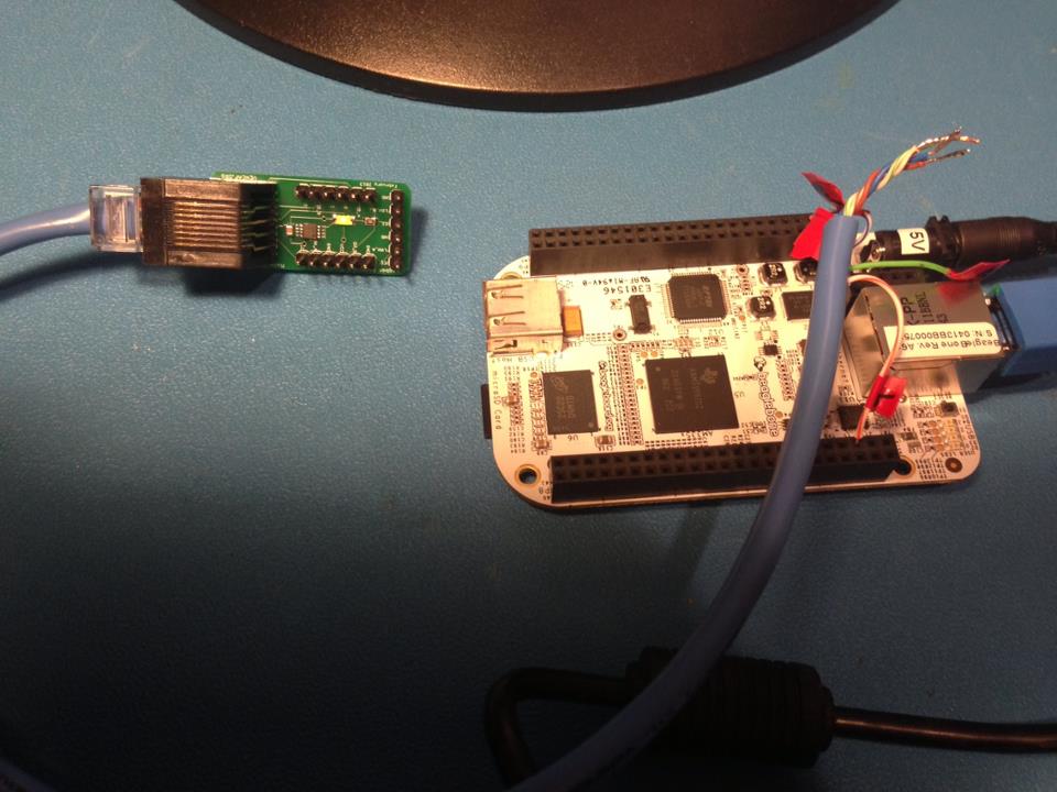
The rows of black header connectors along the long edges of the BeagleBone single-board computer include +5 and +3.3 V DC power rails, ground connections, and input/output interfaces to the ARM Cortex-A8 microprocessor. After connecting the ground and power lines of the Cat5E cable to BeagleBone connector P9 pins 1 and 3, respectively, the BeagleBone sources +3.3 VDC power to the Coaster. The one-wire temperature sensor was plugged into connector P8 pin 3 (GPIO1_6), designated ONE_WIRE_A on the BeagleBeer schematic.
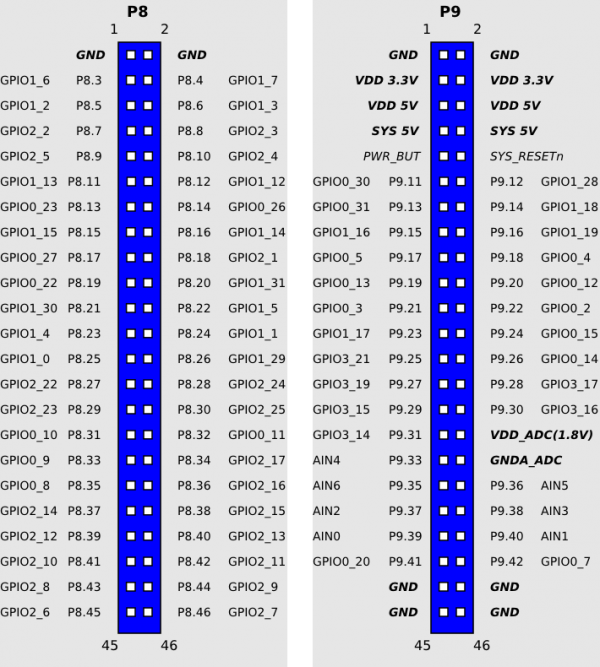
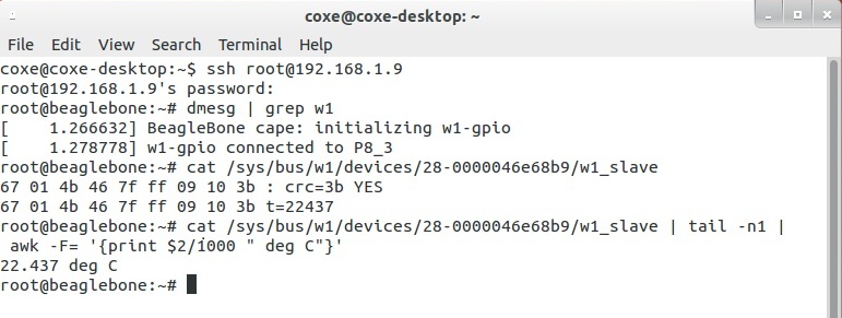
The BeagleBone ships with the Angstrom Distribution of Linux pre-installed. Although the BeagleBone has a myriad of on-board peripherals, it only sports 66 input/output pins. Pin functions can be assigned by software at run time. The supported configurations are documented in exhaustive detail in the BeagleBone Reference manual. A one-wire Linux driver, w1-gpio, is associated with connector P8 pin 6 (GPIO1_3) at power-up. Convincing the BeagleBone to treat P8 pin 3 as a one-wire I/O line required a Linux kernel patch, a diversion that I will not discuss in detail except to say that it was thoroughly dorktastic. After rebuilding the patched kernel and connecting the one-wire line from the Coaster to P8 pin 3, the green LED illuminated (hallelujah!). Eventually, a C, Python, or Javascript program will periodically poll the sensor and output a temperature. However, reading the temperature directly from the w1-gpio driver also did the trick (ignore the bizarre command line syntax):
The DS18B20 temperature sensor can operate at either +3.3 or +5V. In the original Kegbot project, the Coaster board was designed for +5V, the minimum operating voltage for the Swissflow SF800 flow sensors. Furthermore, the Arduino microcontroller used in most Kegbots has +5V-compliant I/O lines. Unfortunately, applying +5V to a BeagleBone +3.3V input pin will fry the board. As we shall see, this seemingly minor detail complicates things quite a bit.
Satisfied with the Coasters, I plugged the BeagleBeer board into the BeagleBone and flipped on a +5V lab supply powering the two boards. Suffice it to say that things did not go according to plan.
The board failed the dreaded Smoke Test. As soon as I turned on the power, I smelled something burning. I immediately switched off the power supply and inspected the board, only to discover that the EEPROM had heated up so much that it had melted all of the solder joints and detached itself from the BeagleBeer printed circuit board. Doh!
The EEPROM stores the name and ID code of the BeagleBeer board in non-volatile memory (values persist in the absence of power) and can be programmed and read back by the BeagleBone. For all practical purposes, removing the EEPROM should not affect the other functions of the BeagleBeer board. The cause of this unfortunate occurrence did not take long to track down—reversed power and ground pins on the schematic symbol.
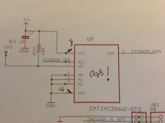
Temporary fix: remove the EEPROM.
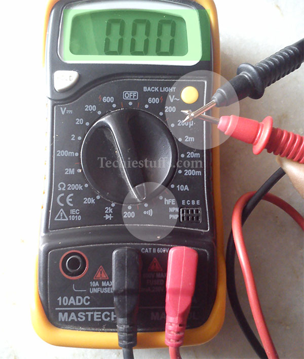
Power on Take 2! No more smoke, thank the gods in these unforgiving times. After a quick temperature check of all of the major components on the board with the tip of my index finger, I measured the voltages on all of the power rails on the BeagleBeer board with a multimeter. The +3.3V connections passed with flying colors. The VDD_5V and SYS_5V lines, connected to BeagleBone connector P9 pins 5, 6, 7, and 8, registered 5.0 V as expected. But all of the +5V lines on the rest of the board appeared to be at 0 V. Doh!
I verified that the 5V power lines and GND were, in fact, not shorted together using the handy continuity test mode on the multimeter. The instrument emits a loud beeping noise when the two test probes are connected.
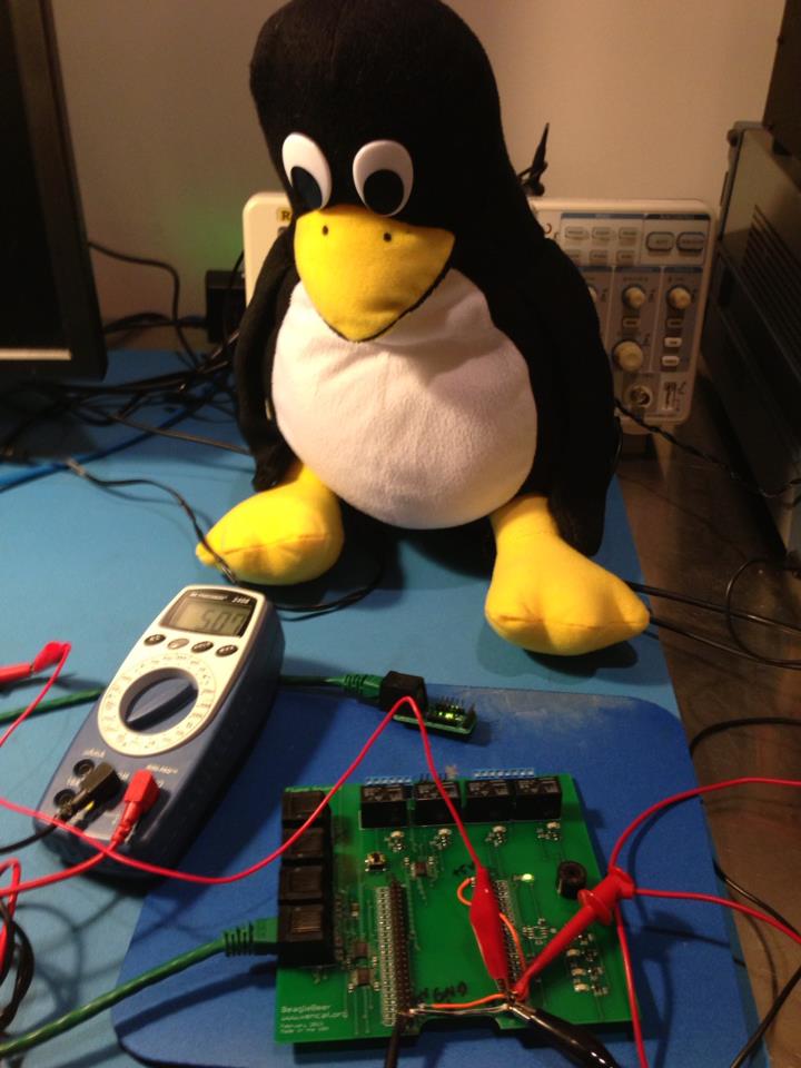
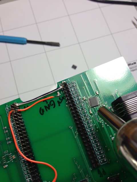
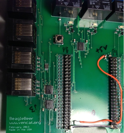
After poring through the BeagleBeer circuit schematic, I failed to identify any obvious knuckleheaded mistakes. A quick glance at the board layout in the Eagle CAD tool, however, revealed the awful truth– nets called 5V (the BeagleBone power pins) and 5.0V (the 5V power rails everywhere else) were, tragically, not connected to each other. Out came the soldering iron for a minor surgical procedure that involved connecting two orange wires from the BeagleBone 5V power pin to the 5.0V nets. I added another GND connection between the two BeagleBone connectors for good measure. Tux the Polyester Penguin inspects the result:
Power woes behind us, Tux and I decided to attempt to read out the temperature sensor on the Coaster through the BeagleBeer controller. Using a Cat5E cable with both ends intact, I plugged the Coaster in to the RJ-45 receptacle on the BeagleBeer. For some as yet to be determined reason, the BeagleBone does not boot when powered on with the BeagleBeer board connected. So, after Linux had booted, the BeagleBeer board was hot-swapped onto the BeagleBone, which, admittedly, was probably not most sensible thing to do.
The power LED on the BeagleBeer illuminated and all seemed well until I attempted to read out the temperature sensor. Linux acted as if no one-wire slave devices were present. I double-checked that the sensor worked standalone. After some head scratching and consultation of data sheets, I zeroed in on the Texas Instruments TXB0108 level translator chips. Because the BeagleBone can only handle digital inputs and outputs up to +3.3V, the +5V inputs from the Coaster board must have the high voltage (corresponding to a binary ‘1’) stepped down to avoid frying the ARM core. To make a long story short, this particular level translator chip will not work for open drain applications like one-wire temperature sensors. Doh!
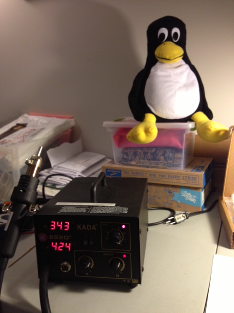
Texas Instruments helpfully suggests replacing the offending TXB0108s with pin-compatible TXS0108s, which include internal pull-up resistors and will play nicely with one-wire devices. The new chips arrived from Digikey within 48 hours. Replacing surface-mount integrated circuits, however, is more easily said than done. Chip removal required The Sketchy Chinese Heat Gun. Tux looks slightly horrified on the photo, and rightly so. The temperature control on this particular unit, acquired several years ago on eBay from a dubious supplier in the Far East, is non-existent. It has two settings—fire of 1000 suns and OFF. (If and when I have more working capital at my disposal, I’ll invest a few thousand dollars in a much more reliable Hakko heat gun from Japan.) To add insult to injury, my soldering skills are mediocre at best. This surgical procedure was considerably more complicated than the +5V power line fix:
1) Melt the old chip off. Easy enough. I somehow managed to prevent surface-mount components that I did not intend to desolder from skittering off the board, never to be seen again.
2) Clean up the solder pads, apply solder flux, and place the replacement chip on the pads. Getting the two TXS0108s in the proper position literally drove me to drink, but I eventually succeeded.
3) Tack down opposite pins of the chip with the soldering iron, then flow a big blob of solder over the remaining pins. The pins were too close together for a mere mortal like me to solder them down one by one.
4) Remove the short circuits between pins with desoldering wick and a tool that looks like a dental instrument.
5) Remove the pullup resistors on the BeagleBeer board with desoldering tweezers.
6) Attempt to clean up the mess with solder flux remover.
Although in principle this fix should have worked, it didn’t. Linux still acts blissfully ignorant of the presence of a temperature sensor. Doh!
The root cause of failure is still under investigation. I have a few more tricks up my sleeve:
1) Ask my co-worker at Analog Devices Lyric Labs, Vlad Kvartenko (a.k.a. master of electronics rework), to replace the TXB0108 chips on BeagleBeer serial number 2 with TXS0108s.
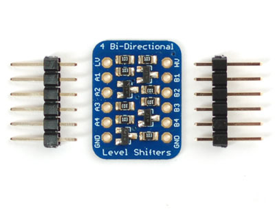
2) Bypass the TXS0108 on BeagleBeer serial number 1 and wire an alternative, the Adafruit Level Shifter module. between the RJ-45 connector and the BeagleBone ONE_WIRE_A line.
The next challenge that must be overcome before the BeagleBeer plus Coaster system can be beta tested with actual beer in the Venture Café kegerator will be to sort out level translation for the flow sensors. Feel free to offer a ritual sacrifice to the Fickle Gods of Electronics Debugging on my behalf and keep an eye out for the next installment, Operation KEG Part 5: It’s Alive!
Random factoid: NASA astronaut Jack Swigert actually said: “Houston, we’ve had a problem here,” after the oxygen tank exploded on Apollo 13 on 13 April 1970.